Phase Angle In Rc Circuit. The exact angle depends on whether the capacitive current or resistive current is greater. in a parallel rc circuit, the line current leads the applied voltage by some phase angle less than 90 degrees but greater than 0 degrees. phase angle and power factor. the impedance phase angle \({\theta}\) of the rc series circuit is expressed by the following equation: learn what an rc circuit is, series & parallel rc circuits, and the equations & transfer function for an rc circuit. analyze the series rc circuit in figure 4 to determine the current, the voltage across r, the voltage across c, and the phase angle of the current. In a series rc circuit connected to an ac voltage source, voltage and current maintain a phase difference. From the phasor diagram shown above, it is clear that the current in the circuit leads the applied.
from electrical-information.com
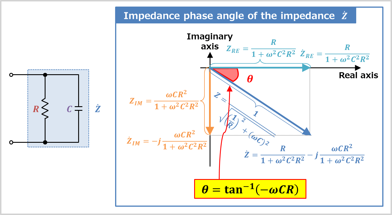
In a series rc circuit connected to an ac voltage source, voltage and current maintain a phase difference. The exact angle depends on whether the capacitive current or resistive current is greater. From the phasor diagram shown above, it is clear that the current in the circuit leads the applied. the impedance phase angle \({\theta}\) of the rc series circuit is expressed by the following equation: phase angle and power factor. in a parallel rc circuit, the line current leads the applied voltage by some phase angle less than 90 degrees but greater than 0 degrees. analyze the series rc circuit in figure 4 to determine the current, the voltage across r, the voltage across c, and the phase angle of the current. learn what an rc circuit is, series & parallel rc circuits, and the equations & transfer function for an rc circuit.
RC Parallel Circuit (Impedance, Phasor Diagram) Electrical Information
Phase Angle In Rc Circuit analyze the series rc circuit in figure 4 to determine the current, the voltage across r, the voltage across c, and the phase angle of the current. In a series rc circuit connected to an ac voltage source, voltage and current maintain a phase difference. The exact angle depends on whether the capacitive current or resistive current is greater. learn what an rc circuit is, series & parallel rc circuits, and the equations & transfer function for an rc circuit. From the phasor diagram shown above, it is clear that the current in the circuit leads the applied. the impedance phase angle \({\theta}\) of the rc series circuit is expressed by the following equation: in a parallel rc circuit, the line current leads the applied voltage by some phase angle less than 90 degrees but greater than 0 degrees. phase angle and power factor. analyze the series rc circuit in figure 4 to determine the current, the voltage across r, the voltage across c, and the phase angle of the current.